Lift Check Valve
- Pressure Rating
- CL150~CL2500
- Connection
- SW, NPT, BW , RF, RTJ
- Design Standard
- BS 1868
- Material
- A216-WCB (Carbon Steel), A217-WC6 (1-1/4Cr-1/2Mo), A217-WC9 (2-1⁄4Cr–1Mo), A217-C5 (5Cr–1⁄2Mo), A217-C12 (9Cr–1Mo), A352-LCB (Carbon Steel), A352-LCC (Carbon Steel), A351-CF8M (18Cr–9Ni–2Mo), A351-CF3M (18Cr–9Ni–2Mo)
Design Features:
Pressure Range: Class 150 ~ 2500
Nominal Size Range: DN 50 ~ 900, NPS 2" ~ 36"
Connection: Flange (RF, FF, RTJ), Butt Welded (BW), Socket Welded (SW)
Lift type disc
Design Specifications:
Design: BS 1868
Wall thickness: API 600
Pressure-temperature rating: ASME B16.34
Face-to-face dimensions for butt weld and flanged valves: ASME B16.10
Flange design: ASME B16.5
Butt welding design: ASME B16.25
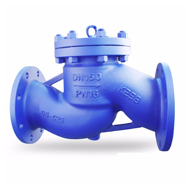
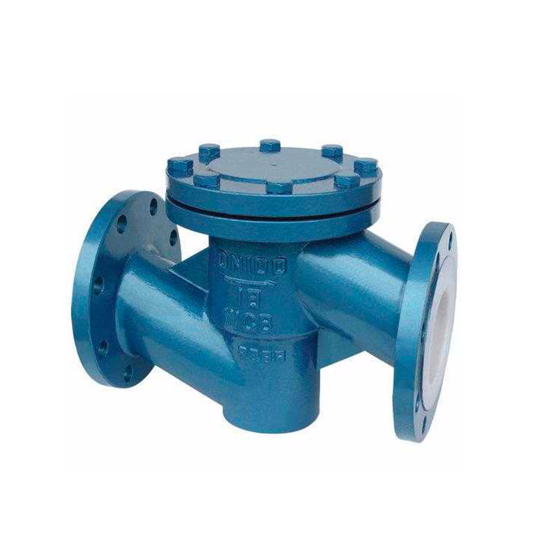
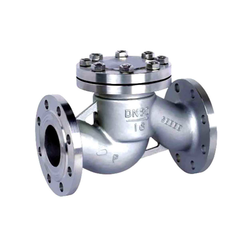
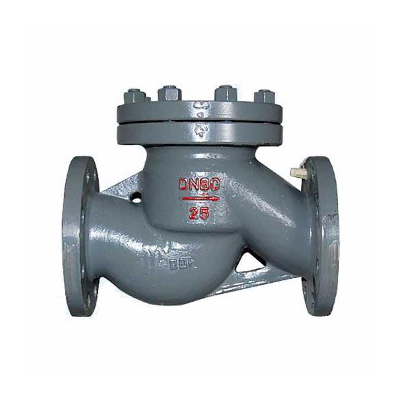
The use of a lift check valve is to prevent back flow into a stream. The valve is used mainly in water applications because of its design. The pressure of the media is what is used to open the lift check valve, which starts off in a normally closed (NC) position.
Furthermore a lift check valve’s process is fully automated because it depends on gravity and the pressure of the media to work. When the pressure increases and reaches its optimal rate, the disk will begin to lift off of the seat, allowing flow to pass through the valve. As the pressure decreases, the cone (assisted by gravity) will begin to return to its original position. As the cone reaches its original starting position, the seal will close and flow won’t be able to pass through the orifice.
Gravity is a large factor in operating a lift check valve, due to this, the valve must be in a horizontal position when in use.
Application:
The areas of industry where lift check valves can be used:
- Pipelines
- Oil and gas
- Food and beverage
- Biopharm industry
- Marine industry

